Timer circuit alarm 555 ic using simple construction working 555 timer circuits How to build a clock circuit with a 555 timer
24 Hour Digital Clock and Timer Circuit - Engineering Projects
Clock signal timer generated pausing using schematic circuit circuitlab created stack 555 timer circuits blinking component 24-hour digital clock and timer circuit
Binary clock project
555 timer circuit ic diagram astable mode tutorial randomnerdtutorials introducingSchematic 555 timer circuit diagram : using the 555 timer ic in special Timer 555 circuit schematic ne555 electronic circuits control diagram ic lm555 charger multivibrator relay off generator applications using switch simple555 timer ic diagram block astable multivibrator circuit using internal.
Adjustable timer circuits using ic 555Clocking circuits 555 timer circuit timers ic diagram works integrated electronics electronic tutorial projects which board vibrators multi popular types most blockHow to build a clock circuit with a 555 timer.

24 hour digital clock and timer circuit
Clock circuit timer digital hour using 555 generator hz pulse icCircuit delay timer Timer graham lambert555 timer circuit using light dancing circuits diagram pcb ne555 chip easyeda 555timer 5v based astable projects delay mode software.
555 timer circuitsElectronic circuits and projects: 555 timer based binary counter circuit 0 to 99 counter circuit using 555 timer and cd4033 icAstable timer eevblog.

Introduction to the 555 timer
Clock circuit digital timer hour 24 diagram electronics electronic projects microcontroller without based simple counter driver circuits crcuitProgrammable timer clock circuit using digital circuits making homemade timing ic ordinated seconds perfectly input therefore pulse acquired main Circuit relay led diagram timer second 555 control circuits using schematic volt seekic delay ic simple indication description555 timer circuits.
555 generator timer pulse ic simple circuit circuits electronic oscillator diagram projects digital voltage wiring arduino electronics ne555n diy logic555 timer basics 555 timer clock circuit schematic build circuitos con using learningaboutelectronics resistor 60hz breadboard produceIc 555 delay timer circuit.

Digital clock circuit using ic 555 and ic 4026 – diy electronics projects
How does a 555 timer work?Dancing light using 555 timer Circuit timer circuits using simple 555 ic diagram switch adjustable buzzer delay connect button electronic ic555 minutes between please pushCircuit 555 clock timer breadboard build schematic.
Circuit viens wenonaIntroduction to timers Timer circuit 555 relay ic circuits switching off projects alternate homemade two alternating astable board diagram switch delay 12v flasher5-20 minuts timer circuit using ic 555.

Clock circuit led timer schema hct pe2bz relay misc blocks
Delay circuit timer 555 simple using circuits 5v power 9v diy switchingTimer 555 schematic 555 timer tutorial and circuitsIntroducing 555 timer ic.
555 timer circuit using adjustable ic variable components required resistor buzzer push buttonLed chaser using 4017 counter and 555 timer Counter circuit binary 555 timer circuits based electronic schematic projects ic diagram using gates diagrams gate circuitdigest choose board electronicsAlternate switching relay timer circuit.

Making a programmable timer circuit using a digital clock
Simple timer alarm circuit using ic 555Timer digital circuit ic stop diagram circuits schematic counter electronics lm555 digit projects electronic segment display simple circuitstoday using led 555 bistable timer multivibrator ic circuits circuitdigest stable monostable schematics4017 555 led chaser timer using counter circuit diagram ic capacitor.
Simple time delay circuit using 555 timerPin on 555 timer circuits [solved] 555 time in astable mode giving "wrong" frequency???Astable multivibrator using 555 timer.

555 clock timer circuit 1hz binary
Adjustable timer circuit using 555555 timer led astable mode flashing photoresistor circuit blinking potentiometer resistor using capacitor light basics flash diagram ohm 7k off Clock digital circuit using ic diy diagram display electronics project segment board clocks arduino basic hub above resolution high click.
.


Adjustable Timer Circuit using 555

Binary Clock Project | Kicken's World
![[SOLVED] 555 time in astable mode giving "wrong" frequency??? - Page 1](https://i2.wp.com/www.jameco.com/Jameco/workshop/techtip/555-timer-tutorial-fig8.jpg)
[SOLVED] 555 time in astable mode giving "wrong" frequency??? - Page 1

Alternate Switching Relay Timer Circuit
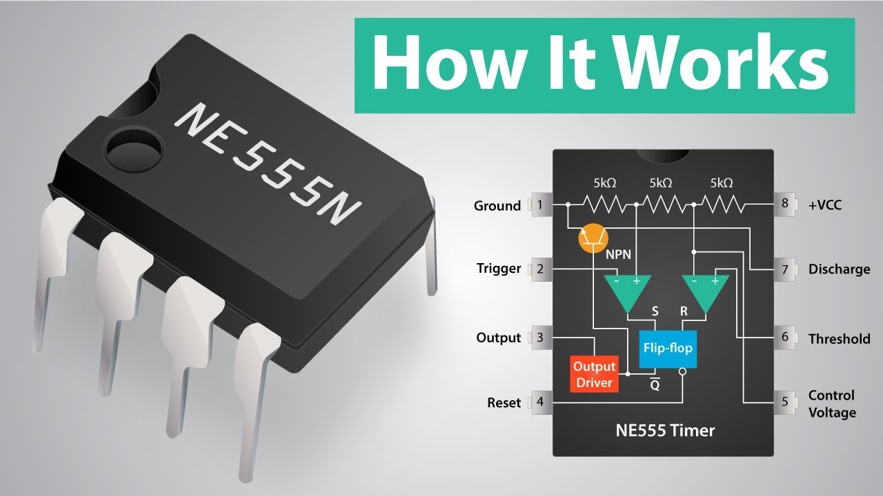
Introduction to Timers | Multi-vibrators | Types of Multi-Vibrators