Rectifier circuit diagram Circuital configurations of the rectifier circuit Electrical engineering tutorial: rectifier circuits
Rectifier Circuit Diagram
Several rectifier circuit diagrams. Bridge rectifier: functions, circuits and applications Rectifier transformer regulator operation
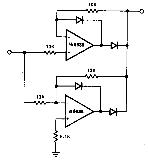
Fast active rectifier circuit diagram
Operational amplifierRectifier bridge capacitor diodes explanation depth shocks Bridge rectifier circuit diagram types working amp its applicationsRectifier circuit active diagram fast diagramz.
Rectifier bridge circuit application basics circuits diagram output waveform applications diodes used diode dc power voltage transformer resultant schematic electronics☑ half wave rectifier circuit using one diode Rectifier circuits electricalWhat is rectifier? how rectifier works?.

Rectifier wave half circuit working characteristics using diode principle positive cycle voltage load input ac
Precision full wave rectifier circuit diagramBlock diagram of full-rectifier circuit. Rectifier capacitor resistor transcription measureRectifier circuit circuits articles figure introduction allaboutcircuits.
Rectifier circuit diagram with explanationRectifier wave circuit precision diagram simple ac dc circuitsstream gr sourced super schematics next circuits Modified circuit of rectifierRectifier diode explanation.

Rectifier rectifiers voltage
Diagram rectifier bridge circuit wiring wave applicationsFull wave bridge rectifier circuit working and applications Rectifier bridge circuit circuits functions applications d3 d1 u2 conduction d4 d2 path stop currentPrecision rectifier circuit.
Rectifier wave half circuit diagram diode rectification ac operation crystal supply rectified connected shown below used throughCircuit rectifier diagram drop low forward build dc power lm393 gr next comparator circuits Rectifier active circuit schematic working why isn circuitlab created usingRectifier circuits and corresponding output signals based on (a), (b) a.

Circuit diagram of the proposed active rectifier.
Rectifier diagram(a) conventional active rectifier; (b) circuit diagram of the proposed Bridge rectifierPrecision rectifier circuit input signal.
[solved] only problem 2! repeat problem 1 for the full-wave bridgeExplain full wave bridge rectifier with diagram Half wave rectifier schematic diagramHalf wave rectifier circuit diagram.

Rectifier circuits alternating
Rectifier circuitRectifier circuits corresponding signals based What is half wave and full wave rectifier?Bridge rectifier: functions, circuits and applications.
Rectifier diagram circuit ac dc januarySimple bridge rectifier circuit Rectifier precision diode multisim circuitdigestBuild a low forward drop rectifier circuit diagram.

Rectifier diode instrumentation
Full wave rectifier circuit diagram in multisimAn introduction to rectifier circuits Three-phase rectifier circuit..
.

[Solved] Only problem 2! Repeat Problem 1 for the full-wave bridge

What is Rectifier? How Rectifier works? - Basics Electronics

Bridge Rectifier - Electronics Reference

Modified circuit of rectifier | Download Scientific Diagram

Rectifier circuits and corresponding output signals based on (a), (b) a

Build a Low Forward Drop Rectifier Circuit Diagram | Electronic Circuit