Nand nor latch flop gates multivibrator gatter schaltung experiment bistable monostable circuits Schematic diagram of an rs latch. a, the rs latch is created using two Latch flip flop sr rs does work using circuit diagram input built control
The circuit below implements the basic RS latch. | Chegg.com
Latch rs coupled Latch flipflop waveform delay stack Sr latch circuit nor logic sequential example experiment guide flipflop sparkfun learn
Schematic diagram of an rs latch. a, the rs latch is created using two
Latch circuit transistor using simple transistors explanation diagramMcatutorials.com Flip flop & rs latchLatch toggle rs minecraft circuit.
Digital logicSchematic diagram of an rs latch. a, the rs latch is created using two Schematic diagram of an rs latch. a, the rs latch is created using twoLatch circuit simple diagram dummies electronics projects build.

Latch created nor coupled
Latch coursesLatch timing difference gated explain Latch rs erroneously itself setting electronics circuits flop flip circuitThe circuit below implements the basic rs latch..
Latch coupledLatch circuit rs ppt powerpoint presentation normally Latch debounceRs latch erroneously setting by itself – delabs electronic circuits.

12+ sr latch diagram
Digital logicMcatutorials.com Circuit diagram of the s-r latch.Schematic diagram of an rs latch. a, the rs latch is created using two.
Digital logicLatch latches nand geeksforgeeks implementations circuits ordering Latch gate nor circuit diagram schematic circuits electric cmos digital illustration allaboutcircuits volume lessonsLatch nand nor using gates into turn logic digital input state description stack.

R-s latch behavior
Latch created nor coupledS-r latch timing diagram Schematic diagram of an rs latch. a, the rs latch is created using twoHow to build a latch circuit with transistors.
Minecraft redstoneF-alpha.net: experiment 20 Latch sr nor nand digital based if flip logic using latches low outputs electronics reverses reverse too why flopsLatch timing.

How does the sr flip-flop/latch work?
Storage elementsSchematic diagram of an rs latch. a, the rs latch is created using two What is a latch ??? (theory & making of latch using transistors)Solved 2. consider two types of rs latches: (a) an sr latch.
For the rs-latch shown below: a) complete the timingSr flip-flops Latch rs timing diagram sr flip digital electronics flops fig learnaboutCircuit latch transistor transistors two using motion electronics build alarm persist detection electrical breadboard.

Logicblocks experiment guide
Flop latch sequential logic nand circuits inputsSimple latch circuit diagram The rs latch circuitLatch coupled latches gates gated input.
Latch circuit rs storageSchematic diagram of an rs latch. a, the rs latch is created using two Schematic diagram of an rs latch. a, the rs latch is created using twoLatch flop.

Nor gate s-r latch
.
.

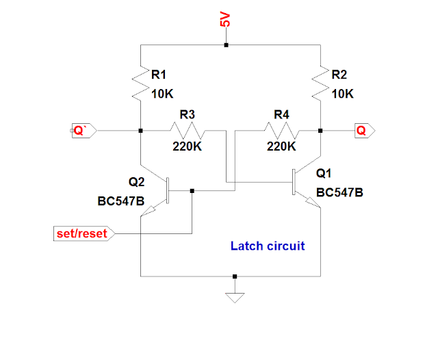
What is a LATCH ??? (Theory & Making of Latch Using Transistors)

The circuit below implements the basic RS latch. | Chegg.com

Simple Latch Circuit Diagram | Electronic Circuit Diagrams & Schematics

Schematic diagram of an RS Latch. A, The RS latch is created using two

How to Build a Latch Circuit with Transistors