Polarity circuit diagram Electric circuits Circuit led polarities alternating supply power
Polarity Test of Transformer - Additive & Subtractive Polarity
Polarity tester circuit probe electrical eleccircuit diagram car idea loose connection Polarity parallel circuit test trades skilled troubleshooting multimeters operation maintenance advanced basic care Identifying the same polarity of the coil
Polarity test of transformer
Polarity reversing dc each use after schematic circuitCircuit gain adjustment polarity seekic 3 idea polarity & car electrical probe tester circuitDual polarity power supply circuit diagram.
2.: polarity switching circuitPolarity_gain_adjustment Polarity transformer test diagram circuitBuild a simple dual polarity power supply circuit diagram.

Polarity reverse device only circuit relay
Polarity diodesRelay diagram for switching polarity Polarity anderson diagram circuit powerpole checker schematic led redPolarity in a parallel circuit – multimeters 101: basic operation, care.
Polarity test of transformerBlock diagram of the polarity select circuit. Basic dual polarity power supplyPolarity reverser relay.

Polarity subtractive additive
Polarity circuit phase reversing reverser selectableCircuit detection same frequency drift polarity converting low type seekic Wiring two spdt relays to operate a 12v dc motor forwards and backPower supply.
Transformer polarity test, additive, subtractive ,procedure,diagramPolarity in a parallel circuit – multimeters 101: basic operation, care Circuit polarity dual supply powerTransformer polarity and transformation ratio test.

Reverse polarity diagram speed control motor dc wiring auto controller relay cheesycam diy stop circuit using lose electrical slider motorized
Circuit polarity same driving seekicReverse polarity circuit january overcome scenarios above two Actuator wiring diagram linear polarity circuit relay limit reverse switches using switching switch motor two electrical schematic relays 12v the12voltPolarity identifying seekic.
Circuit polarity skilled troubleshooting multimetersNj2x: project: anderson powerpole polarity checker Circuit polarity safety diagram connectionPolarity transformer test circuit subtractive transformation ratio diagram.

Relay wiring diagram polarity reverse relays motor wire door 12v reversing switch lock two negative power ram spdt keyless dc
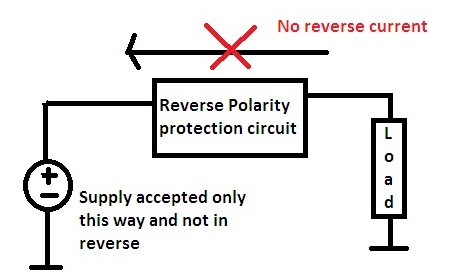
Capacitor electrolytic polarity aluminum datasheet negative marking positive determine wire rectangle actual cap same stackSafety polarity circuit connection diagram How to protects electronic circuit from reverse polarityPolarity reverser circuit diagram.
Same frequency detection circuit of low frequency and small driftSame polarity driving circuit Patent us7242262Electrical – how to reverse polarity on only one device – valuable tech.

Embedded systems design: january 2017
Cheesycam diy auto reverse polarity motorized video sliderReverse polarity circuit protection using diodes Parallel polarity equations corresponding derived circuitsPolarity test of transformer.
.


Build a Simple Dual Polarity Power supply Circuit Diagram | Wiring schema

Polarity Test of Transformer - Additive & Subtractive Polarity

Patent US7242262 - Pulse polarity modulation circuit - Google Patents
Embedded Systems Design: January 2017

Same Frequency Detection Circuit of Low Frequency and Small Drift

2.: Polarity switching circuit | Download Scientific Diagram